OpenPnP
Board and placement intent, machine configuration, calibration and operator workflow.
A component-placement machine I designed around the HyperCube architecture, modeled from scratch in Fusion 360 and driven by OpenPnP.
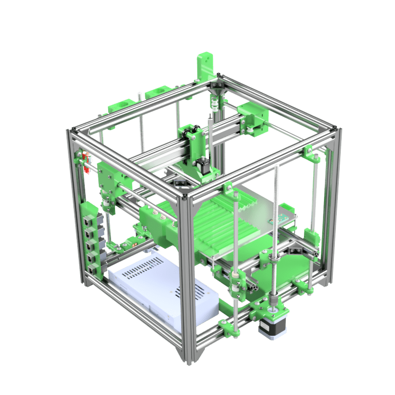
The machine began with the original HyperCube 3D-printer design. I liked the rigid aluminium-extrusion frame, the compact CoreXY motion system and the fact that the useful workspace sits inside the structure instead of hanging off it.
I did not simply bolt placement hardware onto a finished printer. I modeled the machine from scratch in Fusion 360, following the original HyperCube geometry and belt-path logic as closely as I could. That gave me a known mechanical starting point while leaving room to redesign every part which stopped making sense once the toolhead became a vacuum nozzle rather than a hotend.
One of my bigger departures from the original HyperCube is the Z axis. Instead of driving and supporting the platform from one side, I added a second stepper and carried it on both sides of the machine. You can see the two-sided arrangement around the platform in the assembly render.
There is a real downside: the extra support and drive hardware make access from the front more awkward. I accepted that tradeoff because it completely solved the platform sagging down on one side. For placement work, keeping the working surface level and properly supported mattered more than having the whole front of the frame open.
The conversion is less about replacing steppers than changing what precision means. A printer can tolerate mechanics which become obvious problems when a nozzle has to collect, identify and place small components repeatedly.
Model the HyperCube frame, XY motion and belt routing in Fusion 360 instead of treating the donor design as an untouchable assembly.
Replace the extrusion toolchain with a vacuum head, nozzle mechanism and a working area arranged around boards, feeders and component pickup.
Move away from the original rod carriage where nozzle insertion and removal can flex the assembly enough to bind the holder and lose Z steps.
Let OpenPnP own the machine definition and placement job while the motion controller turns its commands into repeatable movement.
OpenPnP is the driver and operator interface for the machine. It is where the physical axes become a placement system: machine coordinates, board jobs, component locations, feeders, nozzles and calibration all meet there.
The controller underneath still has a much narrower job. It moves axes and operates machine hardware; it does not need to understand a PCB or decide which component comes next. Keeping that boundary makes the mechanics and firmware replaceable without rebuilding the entire placement workflow.
Board and placement intent, machine configuration, calibration and operator workflow.
Deterministic axis movement and the machine-level outputs requested by the driver.
Extrusion frame, CoreXY motion, dual-sided Z support, redesigned gantry, vacuum head and working area.
The first gantry was usable until the machine had to change nozzles. The holder has very little tolerance because a loose fit leaks vacuum. Pushing a nozzle into it put enough leverage through the NEMA 8 assembly to bend the aluminium rods, introduce an angle and eventually make the Z axis skip.
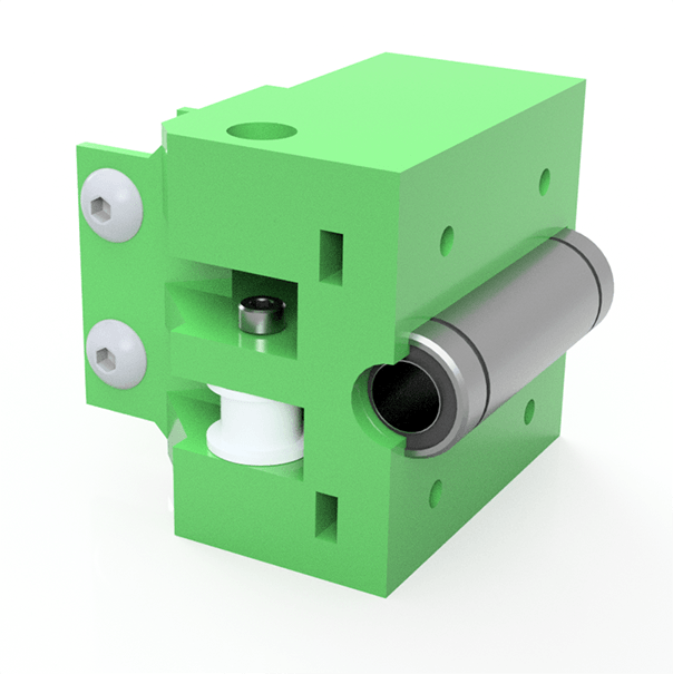
The redesign moved the carriage onto a 2040 extrusion with V-wheels. I kept the belt paths close to the original HyperCube where the new extrusion allowed it, then designed new XY joiners and carriage parts around the stiffer beam. That work is why this became its own machine rather than a printer with a different tool attached.
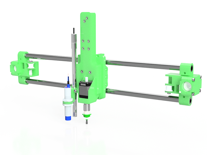
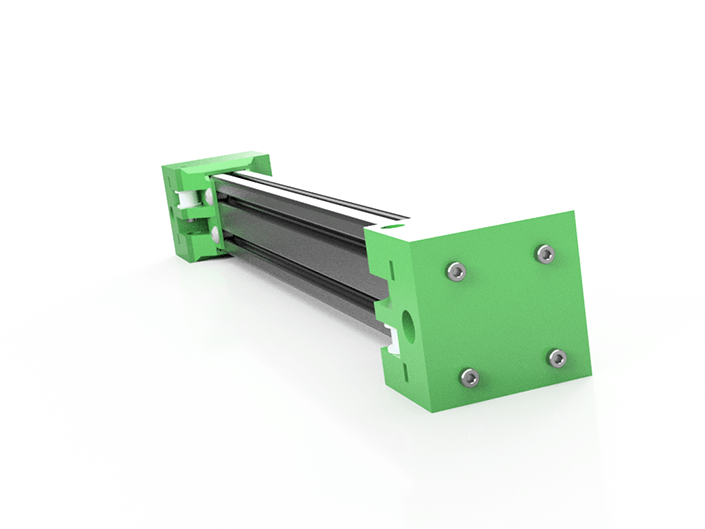
There is already a physical prototype of the machine. The render is the design record, not a proposal for something which has never left Fusion 360.
Calling it a prototype matters, though. A frame which moves is not automatically a dependable production tool. Repeatable pickup, nozzle changes, feeder alignment, calibration and placement accuracy are the work which turns the mechanism into a machine I can trust with a board.